Bus Servo Integration with Mitsubishi FX3U and GX Works2
This guide explains how to integrate Fashion Star bus servos with a Mitsubishi FX3U PLC using GX Works2. It covers UC04 wiring, serial configuration, library import, angle control, and position readback.
1. Wiring Instructions
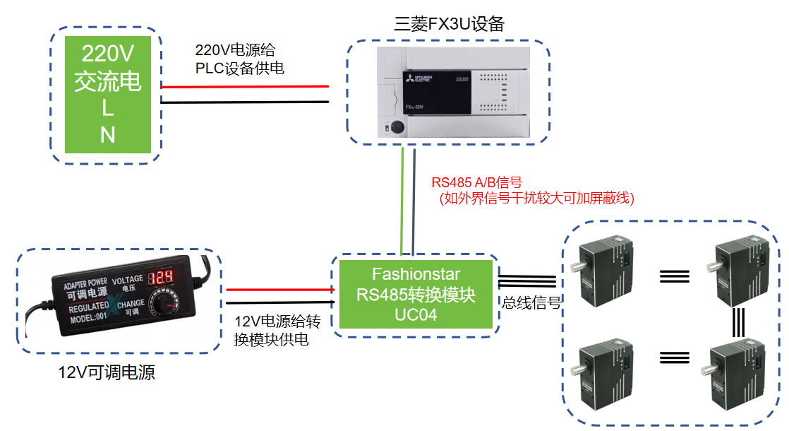
1.1 Device Wiring Architecture
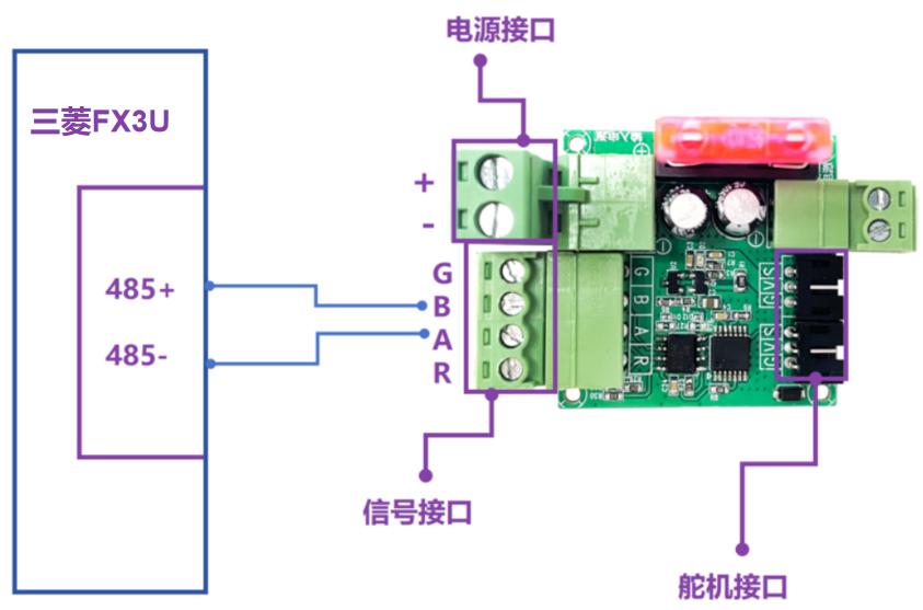
1.2 UC04 Wiring

2. Program Instructions
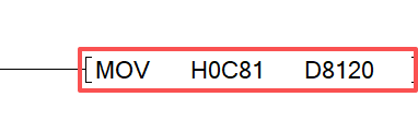
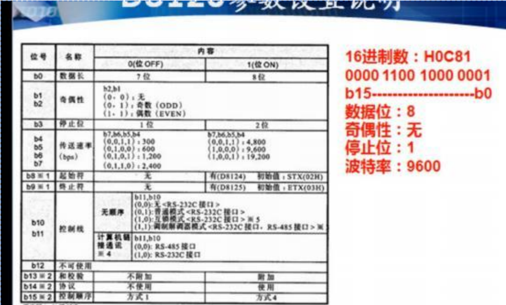
2.1 PLC Serial Port Parameter Setup
- Data bits: 8
- Parity: None
- Stop bits: 1
- Baud rate: 9600
(Because this PLC model does not support 115200 baud, set servo baud rate to 9600 in the PC configuration software.)
2.2 Serial Data Write (via Function Block Library)
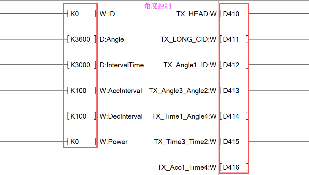
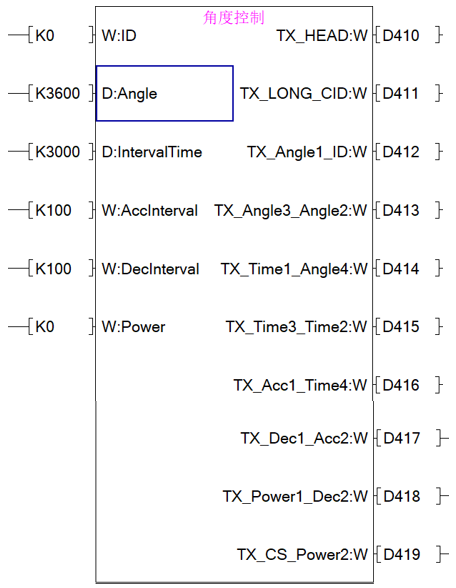
- K0 ------ Servo ID
- K3600 -- Target angle 360.0°
- K3000 -- Reach target in 3000ms (3s)
- K100 --- Acceleration time 100ms
- K100 --- Deceleration time 100ms
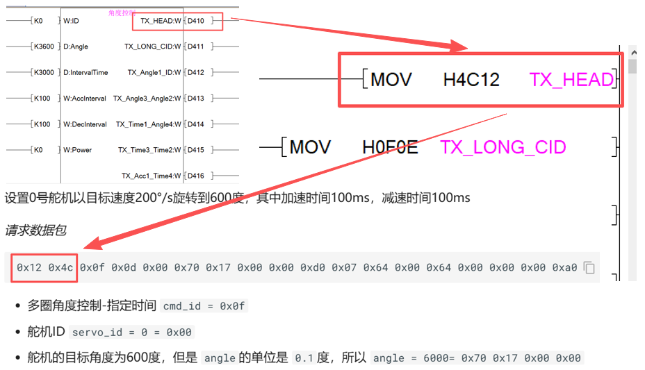
Use function blocks to convert the above data and store it in continuous registers, as shown below: D410, D411, and so on.
2.3 Serial Communication Instruction
- Data to send is stored in D410
- Number of bytes to send is 20
- Response data is stored in D200
- Maximum number of response bytes is 7

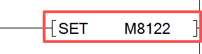
2.4 Serial Send Request
2.5 Serial Port Reset
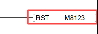
Reference for serial setup:
(018) Mitsubishi FX3U PLC Communication with Serial Assistant - Bilibili
2.6 Function Block and Protocol Mapping
Protocol reference for Fashion Star bus servo communication:
https://fashionstar.com.hk/wiki/protocols/servo/uart-rs485/
- Using the example above (servo ID 0 rotates to 360° in 3000ms), use MOV instructions to store high and low bytes into D410 in order; same rule applies to subsequent registers.
3. Importing Library Files
- In GX Works2, go to Project -> Library Operation -> Acquire Library from Project.
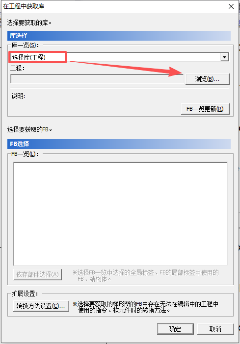
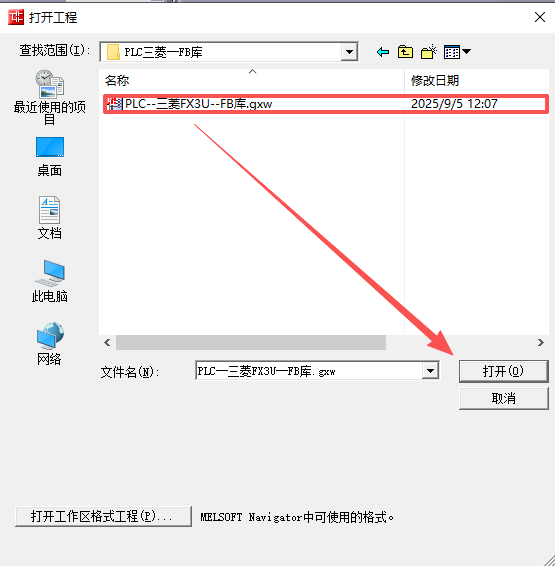
- Import the required library files into the project.
- Drag FB library blocks from FB Manager to invoke them, then write the required control parameters.
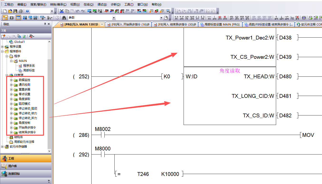
4. Function Block Description
4.1 Angle Control
- ID: servo ID
- Angle: target angle (K3600 means 360.0°)
- IntervalTime: time to reach target angle (K3000 means 3000ms)
- AccInterval: acceleration time (K100 means 100ms)
- DecInterval: deceleration time (K100 means 100ms)
- Power: output power
Note: registers from D410 to the end must be written continuously with no gaps.
(D410 is only an example start register. You can define your own start register; same below.)
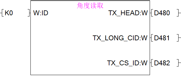
4.2 Angle Readback
- ID: servo ID
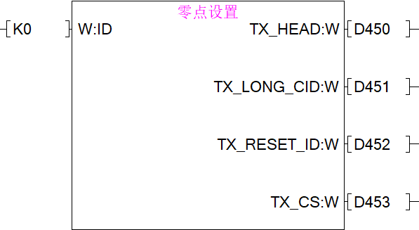
4.3 Home Position Set
- ID: servo ID
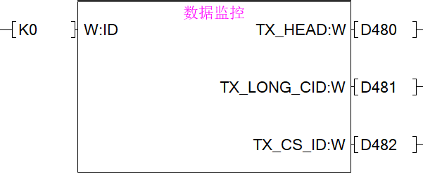
4.4 Data Monitoring
- ID: servo ID
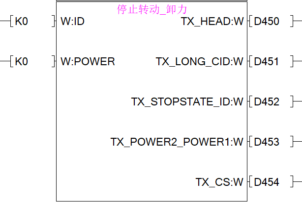
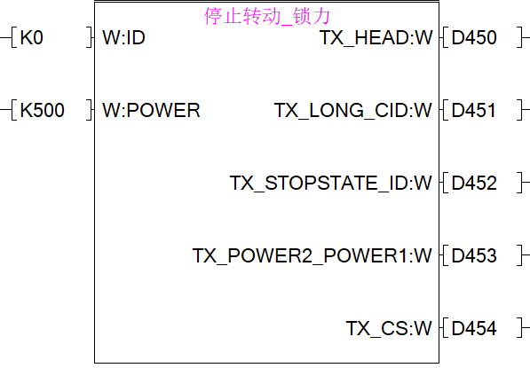
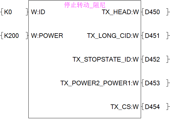
4.5 Stop Rotation - Three Modes
- ID: servo ID
- Power: output power
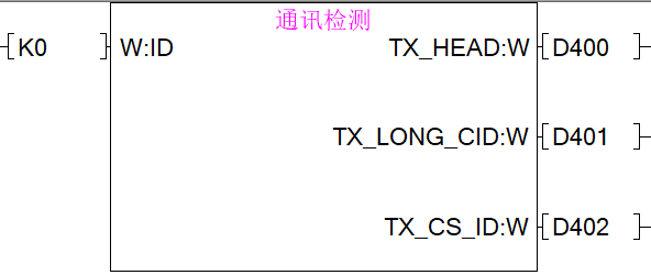
4.6 Communication Test
- ID: servo ID
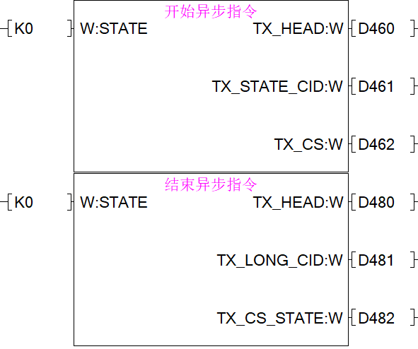
4.7 Async Commands
- Start async command: fixed command, so
STATEdoes not take effect. SetK0. - End async command:
- K0: execute immediately after ending async
- K1: cancel execution after ending async
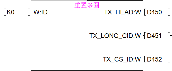
4.8 Multi-turn Reset
- ID: servo ID
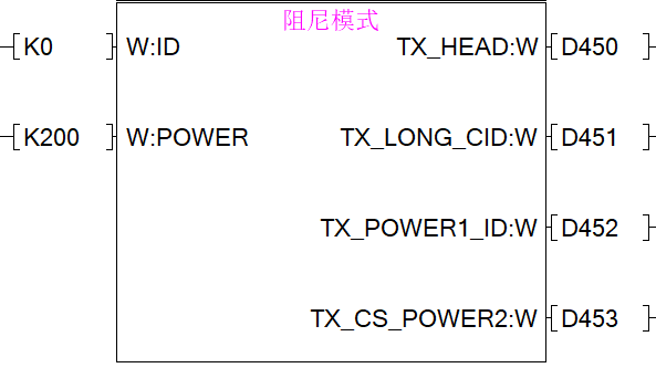
4.9 Damping Mode
- ID: servo ID
- POWER: damping power